Toshiba LCU/SFC OPC Server Configuration Guide
TCP/IP Configuration
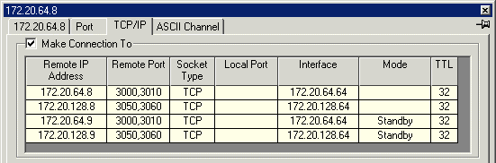
Typical LCU Master configuration
Typical SFC Master configuration
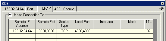
The Remote Port numbers are the Remote Transmit Port, Receive Port numbers
The Local Port numbers are the Local Transmit Port, Receive Port numbers
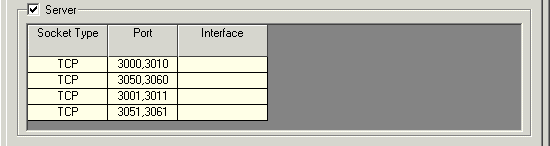
Typical LCU Slave configuration
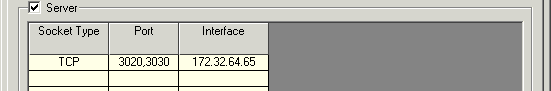
Typical SFC Slave configuration
Channel Configuration
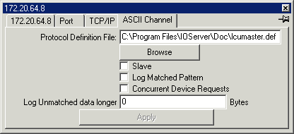
The Toshiba driver uses the User Definable Protocol driver.
| Protocol Definition |
| ||||||||||
|---|---|---|---|---|---|---|---|---|---|---|---|
| Browse | Browse for ASCII protocol definition file. | ||||||||||
| Slave | Not used | ||||||||||
| Log Matched Pattern | Not used | ||||||||||
| Concurrent Device Requests | Not used | ||||||||||
| Log Unmatched data longer than | Set to 0. |
Device Configuration
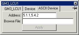
| Address | s.s.s,d.d.d
| ||||||||||||||||||||||||||||||||||||||||||||
|---|---|---|---|---|---|---|---|---|---|---|---|---|---|---|---|---|---|---|---|---|---|---|---|---|---|---|---|---|---|---|---|---|---|---|---|---|---|---|---|---|---|---|---|---|---|
| Browse File | Not Used |
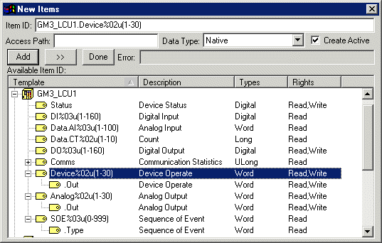
Variable Types
| © Copyright IOServer Pty Ltd. All rights reserved. |
| ✉ sales@ioserver.com 📞+61 2 9805 0356 (Australia) |
|
Last updated: Thu, 16 Jun 2022 08:02:02 GMT |