|
Distributed Network Protocol is an open standard-based protocol maintained by the DNP Users Group (http://www.dnp.org/). The following documentation will only make sense if you have read the documentation published by the DNP Users group. To simplify the interface for OPC clients, the OPC client can only have access to higher-level DNP3 static objects. Instead of having to deal with many separate objects (static object, different variations of the event object, different variations of the output block).
Channel Configuration
| Protocol Mode |
| Master |
IOServer acts as a Master station. |
|---|
| Slave |
IOServer acts as a Slave station. Each DNP3 slave device can support multiple DNP3 masters with access to their independent event buffer. The DNP3 slave will accept requests from any Master Station Address. Each DNP3 Master with the same Master Station Address shares the same event buffer, that is filled from the main event buffer. |
|---|
|
|---|
| Master Station Address |
The address of the Master station. |
|---|
| Offline Quality |
The OPC Quality flag of offline objects (online bit cleared or restart/communication lost bits not cleared).
| C0 |
Quality Good |
|---|
| D8 |
Quality Good, Local Override |
|---|
| 08 |
Quality Bad, Not connected |
|---|
|
|---|
| Connect Ping Type |
Master device Application Layer Initial poll message.
| None |
Class 1, 2, or 3 as configured and Class 0 polls. |
|---|
| Delay Measurement |
Use Delay Measurement. This ensures that the slave clock is synchronized before the event data are polled. The DNP3 Master or Slave can initiate the Time Synchronization procedure by writing 1 to .NeedTime. |
|---|
| Class 0 |
Class 0 poll only. |
|---|
| Request link status with self-address |
The DNP3 master will issue a request link status with self-address of 0xFFFC to identify the slave to be associated with this connection. The request link status will not be issued if the first message (comma- separated list of numbers terminated by \r\n) received on the connection identify any of the configured slaves.
Only DNP3 slaves with this option enabled will respond to requests with self-address. |
|---|
|
|---|
| File Transfer Directory |
If not blank, then restrict all file transfer activities in the slave to this directory. |
|---|
| Force all devices online at startup |
Put all devices attached to this port online at startup. For multi-dropped devices when each device takes more than 30 seconds to start up. |
|---|
| Parallel Access |
When attaching multiple devices to a port, each device can access the port anytime without waiting for another device to finish. For use only when the underlying media have robust collision avoidance handling. |
|---|
| Data Link Confirm Mode |
| Never |
Never request for Data Link confirmation. Disable link layer retry. |
|---|
| Always |
Always request Data Link confirmation. The port.Timeout is used as the link layer timeout, the port.Retries is used as the link-layer retry. |
|---|
| On multi-frames only |
Request Data Link confirmation on multi-frames only. |
|---|
Data Link confirm mode should be turned on when using unreliable media. Turning on the Data Link confirm mode will slow down the data transfer rate. |
|---|
| Ethernet Time Synchronization |
Data Link Confirmation mode is set to Never. Use Record Current Time (Function Code 24) instead of Delay Measurement (Function Code 23) to synchronize time on the Slave. Do not enable this option if your TCP/IP RTU does not support Function Code 24 |
|---|
| Log Link Layer |
Log Link Layer messages to log file. Logging will slow down the data transfer rate. |
|---|
| Application Confirm Mode |
| Never |
Never request for application confirmation. DNP3 Master should use "Never" because the same data will available on the next poll. |
|---|
| Always |
Always request application confirmation. |
|---|
| Sometimes |
Request application confirmation on multi-fragments or when sending event data. |
|---|
| Events |
Request application confirmation when sending event data. DNP3 Slave should use "Events" so that events will only be removed from the buffer when they are acknowledged. |
|---|
|
|---|
| Application Timeout |
Maximum time to wait for an application confirmation or fragment. The application timeout must be greater than (Port Timeout * (Port Retries + 1)). The minimum, maximum, mean and standard deviation of the last sixteen response times are displayed. |
|---|
| Application Retries |
Number of retries before abandoning transactions and putting the device offline. Reconnection will be attempted after Port Watch Time. The Port Watch Time must be greater than (Application Timeout * (Application Retries + 1)) |
|---|
| Application Fragment Size |
Maximum size of each application fragment (200 to 16000). |
|---|
| Log App Layer |
Log Application Layer messages to log file. Logging will slow down the data transfer rate. |
|---|
Device Configuration
| Slave Station Address |
Station Address of Slave. A device with an address of 65535 is used to send broadcast commands such as Freeze or Operate to all devices on a channel. |
|---|
| Device Startup Mode |
Initial value of the .Enable tag of the device.
| Enable |
1 - The device is started and polled as scheduled. |
|---|
| Standby |
2 - The device is started, but the polling schedule is suspended. |
|---|
| Disable |
0 - The device is not started or polled |
|---|
|
|---|
| Timestamp Offset |
Add this number of minutes to timestamps |
|---|
| Object File |
The value of DNP objects is written to this file at the device shutdown. The next time the device is started up, it will use this information to restore the time stamp of DNP objects. Leave this field blank if restoration of the timestamp is not necessary, otherwise specify a different filename for each device. Writing a 0 value to .Backup will cause the current values of all objects to be written to this file. Writing a 1 value to .Backup will restore the values from this file. |
|---|
| Object File Update Time |
The DNP3 Master will ensure that all changes to static objects are saved to the object file within this time. The DNP3 Slave will ensure a new object file is loaded within this time. Set to 0 to disable this feature. e.g. A value of 0.1 in a DNP3 master will ensure that all changes to static objects are saved to the object file within 0.1 seconds. |
|---|
| Use UTC Time |
If Enable, all timestamps read and written to the slave are assumed to be based on UTC (Coordinated Universal Time) time. Otherwise, local time is used. The use of UTC time is recommended, it is the responsibility of each OPC client in different time zones to convert the UTC time to local time for display. |
|---|
| Log SOE |
Log SOE (Sequence of Events) to log file when generated by the slave or received by the master.
11:45:10.005 999 SOE Master.2.3.0,81,2002 01 23 11:45:10.001
| 11:45:10.005 |
Time this event is received. |
| 999 |
Elapsed time since the last event in the log file. |
| SOE |
DNP3 Log tag |
| Master.2.3.0 |
DNP3 event object 2, variation 3 and index 0 from device Master |
| 81 |
Status value (hex) |
| 2002 01 23 11:45:10.001 |
Time as received in the event data |
11:23:54.003 999 SOE Master.32.4.0,01,122,2002 01 23 11:23:54.002
| Master.32.4.0 |
DNP3 event object 32, variation 4 and index 0 from device Master |
| 01 |
Status value (hex) |
| 122 |
Value (decimal) |
| 2002 01 23 11:23:54.002 |
Time as received in the event data | |
|---|
| Poll Type |
Class 0 are static data, these are the current value of the data in the RTU. Class 1, 2, and 3 are event data, these are data changes (possibly with timestamp) of the data in the RTU. Each event object in the RTU can be assigned to classes 1, 2, or 3. Belonging to a class does not imply any sort of priority. Most RTU will statically assign a default class to each event object. More advanced RTU allows the user to assign the class of each event object. Level 3 RTU allows the Master to assign the class of each event object dynamically. Event data are used to update the DNP3 Master database. Event data are normally polled at a much faster rate than static data. Class 0 poll is issued at a very slow rate to the DNP3 Master database is up to date. The RTU will respond with all its static data points to a class 0 poll, which could be quite substantial for a large RTU. The RTU will respond only with data changes to class 1, 2, or 3 polls. |
|---|
| Poll Interval |
Interval between poll for that poll type. A poll interval of 7 seconds with a sync time of 0 seconds means that the master will poll the device at the following times (starting from midnight): 0,7,14,...,63,70.
Class 0 poll should be issued as infrequently as possible because they can use a lot of bandwidth. Events are polled more frequently than static data because they use less bandwidth. If a change is detected first in static data, the data will have the timestamp of the current time. Events will have the correct timestamp. To ensure changes are reported first in event data, class 0 poll is prefaced by event polls.
The Device Polling schedule can be paused by writing a value of 2 to the Device.Enable tag. Other possible values are:
| Write Value |
Action |
|---|
| 0 |
Stop that device immediately and put that device offline. IOServer will continue to restart that device at every watchtime but will be unsuccessful. |
|---|
| 1 |
Allow the device to start successfully at the next watchtime. |
|---|
| 2 |
Suspend polling of the device. The device will remain online. |
|---|
Device.Enable will return a value of 0 if the device is offline. |
|---|
| Sync Time |
Start of poll time within the poll interval. A poll interval of 7 seconds with a sync time of 2 seconds means that the master will poll the device at the following times (starting from midnight): 2,9,16,...,65,72. |
|---|
| Unsolicited |
Enable the reception or transmission of unsolicited messages for that class |
|---|
| Items |
Maximum number of items requested per class poll (supported only by level 2 slaves). Use 0 for no limit. This is used to limit the amount of data that a level 2 slave may return per poll. Use -1 to stop DNP Master from issuing an event poll whenever the class internal indication flag from the RTU is set for this class. Use -1 to stop DNP Slave from setting the class internal indication flags. |
|---|
| Objects |
List of objects/data points to be assigned to this class (supported only by level 3 slaves). Assigning a data point to class 0 stops that slave from producing an event object for that data point. Examples of objects:
| 1 |
All variations and indexes of object 1 |
| 1.1 |
Variation 1 of object 1 |
| 1.1.1-20 |
Indexes 1 to 20 of variation 1 of object 1 | Default class assignment
| Class 0 |
All static data and Output Events(10 12 40) |
|---|
| Class 1 |
All Binary Input Events(1) |
|---|
| Class 2 |
All Analog Input Events(30 31) |
|---|
| Class 3 |
All Counters Events(20 21) |
|---|
When defining your class assignments, first clear the default class assignments by setting Class 0 to "1 20 21 30 31" |
|---|
| Enable SOE Tag |
When enabled in a DNP3 master, all received DNP3 event objects will route to the .SOE tag. Writes to the .SOE tag will cause a DNP3 event to be generated in the DNP3 Slave.
The .SOE tag is string (VT_BSTR) with the format
Digital : object.variation.index,status(hex),optional timestamp
Analog: object.variation.index,status(hex),analog value,optional timestamp |
|---|
| Use Level 3 commands |
Enable Level 3 commands, this option should only be enabled if the RTU support the following level 3 command:
Start/Stop Qualifiers in Poll and Freeze commands
Pattern Control Block and Pattern Mask objects
Assign class
Enable/Disable Unsolicited Message |
|---|
| Enable Freeze |
Writing to analog inputs will cause FREEZE command to be issued, otherwise WRITE command will be issued. |
|---|
| Read after Operate |
Perform a read after operating the output.
| Specific poll |
|
|---|
| Class 0 static poll |
|
|---|
| Class 1 event poll |
|
|---|
| Class 2 event poll |
|
|---|
| Class 3 event poll |
|
|---|
| Read Delay |
Millisecond delay before issuing the read |
|---|
|
|---|
| Event Statistics |
Shows the number of events in the main event buffer and master station event buffers. Address(All,Class 1,Class 2,Class 3:Total:Age) shows the number All, Class 1, Class 2, and Class 3 objects waiting for transmission to master station Address. Total is the number of objects processed so far. Age is the oldest event in the buffer in hours. |
|---|
| Enable Unsolicited Messages |
Enable the transmission of unsolicited messages for Slave. |
|---|
| Execute Pulse on/off commands |
Pulse on/off, Close and Trip commands from the DNP master are executed with the correct on/off time. If disabled, the command from the DNP master is encoded as a 32-bit value that can be passed on to other DNP masters. |
|---|
| Time Offset |
Time offset between clocks on Slave station and Master station. Each DNP3 slave clock must be accurate, but the actual clock of each DNP3 slave can be set to any time or not set all. With DNP3 time synchronization, each DNP3 slave will automatically adjust the timestamp it sends to the master based on the time difference it calculated during the time synchronization procedure. In IOServer DNP3 slave this time offset is displayed in DNP Slave.Time offset. If you want the DNP3 slave to send unsynchronized time, then you will need to turn off time synchronization by clearing the Needtime internal indication before a DNP3 master connects to it.
The following OPC Gateway item will turn off the Needtime internal indicator as soon as the device comes online.
Source: 0
Destination: Device.80.1.NeedTime
Trigger: Device.Status |
|---|
| Event Lifetime |
Event data older than Event lifetime are discarded by the slave. Each writes to an object will cause an event to be generated. To support multiple DNP3 masters, events acknowledged by a DNP3 master are not deleted from the main event buffer. Ensure that the computer is capable of storing the configured number of hours. A value of 0.5 will discard all events older than 30 minutes. The number of events currently stored in each class is indicated by Events(Total, Class 1, Class 2, Class 3). |
|---|
| Event Update Time |
Unsolicited data buffer time, a value of zero means that events are sent immediately. A non zero value allows the slave to pack more events into a single frame for transmission to the master. |
|---|
| Binary Input Change with Relative Time |
When sending more than N Binary Input Change with Time (2.2) objects, convert them to Time and Data (51.1) and Binary Input Change with Relative Time (2.3) objects. |
|---|
| Control Output Close Address Offset |
A close command (Pulse On/Close:65) to control output x will cause the control output x + offset to be operated. |
|---|
Variable Types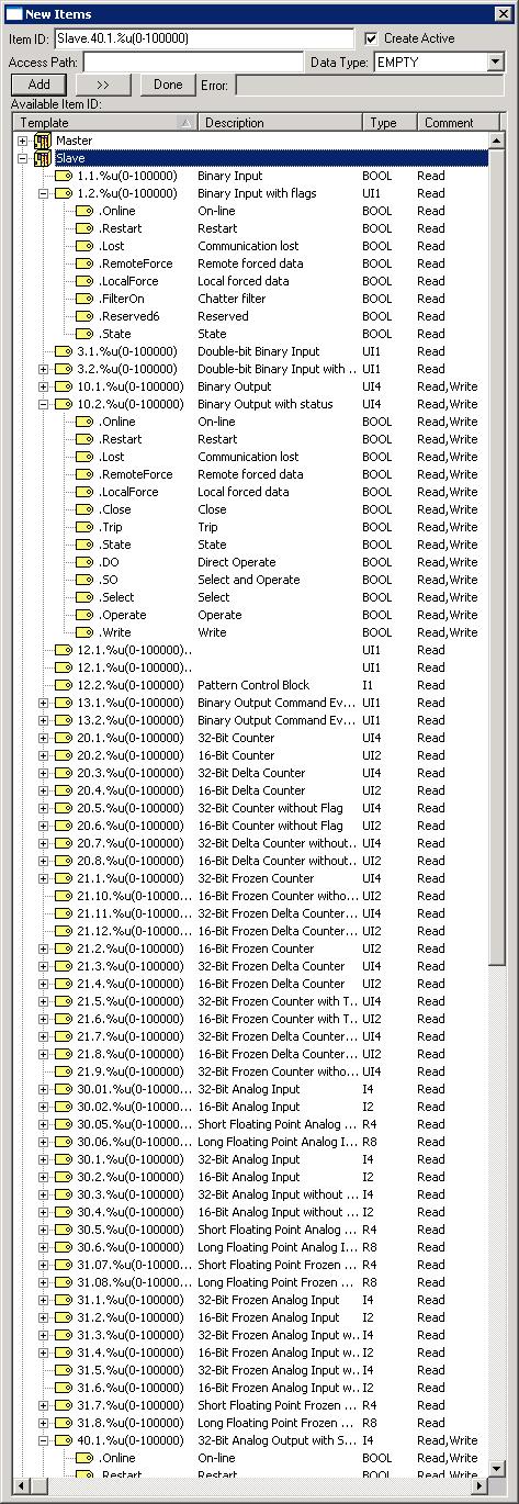
The OPC Browse Server Address Space will show all the available data of each Slave station based on information received from the Slave station. To find out what type of data is available, connect to IOServer, using the built in OPC Server explorer, add a group then add item to see the available data types.
1.2.1 is the 8 bit byte value of the status (online, state and etc.,) of Object 1, variation 2, index 1.
1.2.1.State is the Digital value of the state of object 1, variation 2, index 1.
1.1.1 is the Digital value of the state of object 1, variation 1, index 1.
IOServer DNP3 Device Profile
| Vendor Name: |
IOServer Pty Limited |
|---|
| Device Name: |
IOServer DNP3 Device |
|---|
Highest DNP3 Level Supported:
| For Requests |
3 |
|---|
| For Responses |
3 |
|---|
|
Device Function:
Can be configured as a Master or a Slave at DNP3 Channel Tab, Protocol Mode. |
Maximum Data Link Frame Size (octets)
| Transmitted |
292 |
|---|
| Received |
292 |
|---|
|
Maximum Application Fragment Size (octets)
| Transmitted |
Configurable between 200 and 16000 |
|---|
| Received |
2048 |
|---|
|
| Setting the Application Layer Fragment Size to less than 249 will stop the device from sending Multi-fragments. |
Maximum Data Link Retries
Configurable at Port->Retries, range 0 to 5 |
Maximum Application Layer Retries
Configurable at DNP3 Channel->Application Layer Retries, range 0 to 15 |
Data Link Layer Confirmation: Configurable as
| Never |
Never request for Data Link confirmation. |
|---|
| Always |
Always request Data Link confirmation |
|---|
| On multi-frames only |
Request Data Link confirmation on multi-frames only |
|---|
|
Application Layer Confirmation: Configurable as
| Never |
Never request for application confirmation |
|---|
| Always |
Always request application confirmation |
|---|
| Sometimes |
Request application confirmation on multi-fragments or when sending event data. |
|---|
Defaults to Never for Master and Sometimes for Slave station |
Timeouts while waiting for:
| Data Link Confirm |
Configurable as Port->Timeout between 10 and 360000 milliseconds. |
|---|
| Complete Application Fragment |
Configurable as DNP3 Channel->Application Layer Timeout between 10 and 360000 milliseconds. |
|---|
| Application Confirm |
|---|
| Complete Application Response |
|---|
|
Send/Executes Control Operations
| Write Binary Outputs |
Use .Write suffix in object name |
|---|
| Select / Operate |
Use .SO suffix in object name. The operate will only be issued if the select is successful. |
|---|
| Direct Operate |
Use .DO suffix in object name (Direct operate is chosen if no qualifier is selected) |
|---|
| Direct Operate - No ACK |
Use .DO suffix in object name when writing to the broadcast device. |
|---|
| Select |
Use .Select suffix to only issue the select command. |
|---|
| Operate |
Use .Operate suffix to only issue the operate command. |
|---|
| Freeze |
Writing a zero value to counters or analog inputs will cause the Freeze and Clear command to be issued. Writing a non-zero value will cause the Freeze command to be issued. The no ack version is used when writing to the broadcast device. |
|---|
| Time Synchronization |
The master can initiate time synchronization with any slave by writing any value to the write-only object "50.1.WriteOnly" of that slave. A read request to "50.1" will return a 32-bit value from the slave of the number of milliseconds since midnight. |
|---|
For binary outputs, the 12.1.x.Status will be set to 255 when the write command is issued. The result code of the response will be reported in 12.1.x.Status. A value of zero indicates that the command was accepted. A non zero value indicates failure.
For analog outputs, the 41.x.x will be set to 255 when the write command is issued. The result code of the response will be reported in 40.x.x
Writing to the output object by OPC/DDE clients will cause output block to be written to the RTU:
| Output Type | Data Type | Output | Output Block |
|---|
| Binary Output without Status | Binary |
10.1 |
12.1, 12.2, or 12.3 |
|---|
| Binary Output with Status | Binary |
10.2 |
12.1, 12.2, or 12.3 |
|---|
| Analog Output | 32 Bit |
40.1 |
41.1 |
|---|
| 16 Bit |
40.2 |
41.2 |
|---|
| Short Real |
40.3 |
41.3 |
|---|
| Long Real |
40.4 |
41.4 |
|---|
After the response to a write to output is received, a read is issued to read back the new value of the output. After the write, the result code of the operation is available in 12.1 for binary outputs and 41.x for analog outputs. The meaning of the result code are:
| 0 |
Request accepted, initiated, or queued. |
|---|
| 1 |
Request not accepted as the operate message was received after the arm timer timed out. The arm timer was started when the select operation for the same point was received. |
|---|
| 2 |
No previous matching select message (i.e. an operate message was sent to activate a control point that was not previously armed with the select message). |
|---|
| 3 |
Request not accepted as there were formatting errors in the control request (either select, operate, or direct operate). |
|---|
| 4 |
Control operation not supported for this point. |
|---|
| 5 |
Request not accepted, as the control queue is full or the point is already active. |
|---|
| 6 |
Request not accepted because of control hardware problems |
|---|
| 7 |
Request not accepted because Local/Remote switch is in Local position |
|---|
| 10 |
Request not accepted because it was prevented or inhibited by a local automation process. i.e. .LocalForce of that point is set. |
|---|
| 255 |
Set by the driver, when the command is issued. |
|---|
The maximum number of CROB (Control Relay Output Object 12.1) objects issued in a single message is limited by the Input Queue Length parameter for that port.
The maximum number of analog output (41.x) objects issued in a single message is limited by the Input Queue Length parameter for that port.
Pattern Control Block and Pattern Mask (12.2 and 12.3) are only issued if the Use Level 3 command option is enabled and the Input Queue Length parameter for that port is greater than one.
CROB (12.1) and analog output (41.x) are permitted together in a single message. Binary Outputs
Binary Output with status (10.2) and Binary Output (10.1) are declared as unsigned long, the 32 bit value is interpreted as follows:
Bits 0..7 (8 bits) is the Control Code.
| Control Code | Action |
|---|
| 1 |
Pulse On - The point is turned on for on time, then turned off for off time. |
|---|
| 2 |
Pulse Off - The point is turned off for off time, then turned on for on time. |
|---|
| 3 |
Latch On |
|---|
| 4 |
Latch Off |
|---|
| 65 |
Pulse On/Close |
|---|
| 129 |
Pulse On/Trip |
|---|
| +16 |
Queue |
|---|
| +32 |
Clear |
|---|
Bits 8..15 (8 bits) is Count - 1. i.e. Use a value of zero to specify a count of 1.
Bits 16..22 (7 bits) is the pulse on time.
Bits 23-29 (7 bits) is the pulse off time.
Bit 30-31 (2 bits) is the pulse time factor.
For pulse on/pulse off code with a count of 1 and not queued, Bits 16..29(14 bits) is the pulse time
| Time Factor |
Step Size |
7 Bit Pulse |
14 Bit Pulse |
|---|
| 0 |
1 ms |
Up to 127 ms |
Up to 16.384 seconds |
|---|
| 1 |
100 ms |
Up to 12.70 seconds |
Up to 1638.4 seconds |
|---|
| 2 |
10 seconds |
Up to 1,270 seconds |
Up to 163,840 seconds |
|---|
| 3 |
1000 seconds |
Up to 127,000 seconds |
Up to 4,294,000 seconds |
|---|
Writing a 0 or 1 to "10.2.x.State" object will cause control code 4 or 3 to be written to the output block object respectively.
Writing a 2 to 10.2.10 will pulse 10.2.10 off with Direct Operate.
Writing a 1 to 10.2.10.SO will pulse 10.2.10 on with Select and Operate.
Writing a 1 to 10.1.10.SO,bool will latch on 10.2.10 with Select and Operate.
Writing a 0 to 10.2.10.State will latch off 10.2.10 with Direct Operate.
Writing 845416705 (hex 0032640901) to10.2.10.SO will pulse 10.2.10 on 10 times with 100ms on and 100ms off time with Select and Operate.
Writing 0 to Device.10.1.2.SO.3000,bool will issue control code 2 (Pulse Off) with an off time of 3000 ms with Select and Operate
Writing 1 to Device.10.1.2.DO.3000,bool will issue control code 1 (Pulse On) with an on time of 3000 ms with Direct Operate.
Writing 0 to Device.10.1.2.SO.3000.1,bool will issue control code 129 (Trip/Pulse On) with an on time of 3000 ms
Writing 1 to Device.10.1.2.SO.3000.1,bool will issue control code 65 (Close/Pulse On) with an on time of 3000 ms
The .SO and .DO works similarly for analog outputs. | |
Master Devices will accept both time-tagged and non-time-tagged for all event data. The Time of Occurrence in received event data will be used as the item timestamp for the static data. If none is available then the time when the data is acquired is used. Each item reported by our OPC Server to any OPC client contains the value, timestamp, and quality of the item. This is a standard feature of OPC.
Every single SOE received from the slave RTU will be reported to the interested OPC client via the static data. It is up to the OPC client to accept (not ignore) and use the VTQ (value, timestamp, and quality) information correctly. IOServer will never issue multiple changes for a particular object in each advice to the OPC client. You can insert a delay between each advice by setting the Preference.SOE Interval parameter. Try to use as small value as you can (less than 50ms).
e.g. If the slave reports 2.3.0 (Binary Input Change with relative time), then the OPC client can see the new value and timestamp in 1.1.0 or 1.2.0.State |
Slave Devices
| Objects.variations in the slave are only created when they are first read or written to by OPC/DDE clients. |
Writing to the static object by OPC/DDE clients will cause associated event object to be reported. e.g. Writing to static object 1.1.0 will create a 2.1.0 event object. Writing to static object 1.2.0.State will create a 2.2.0 event object.
| Object Type | Data Type | With Time Object | Without Time Object |
|---|
| Static | Event | Static | Event |
|---|
| Binary Input | Binary |
1.2 |
2.2 |
1.1 |
2.1 |
|---|
| Counter | 32 Bit |
20.1 |
22.5 |
20.5 |
22.1 |
|---|
| 16 Bit |
20.2 |
22.6 |
20.6 |
22.2 |
|---|
| 32 Bit Delta |
20.3 |
22.7 |
20.7 |
22.3 |
|---|
| 16 Bit Delta |
20.4 |
22.8 |
20.8 |
22.4 |
|---|
| Frozen Counter | 32 Bit |
21.1 |
23.5 |
21.9 |
23.1 |
|---|
| 21.5 |
23.5 |
| 16 Bit |
21.2 |
23.6 |
21.10 |
23.2 |
|---|
| 21.6 |
23.6 |
| 32 Bit Delta |
21.3 |
23.7 |
21.11 |
23.3 |
|---|
| 21.7 |
23.7 |
| 16 Bit Delta |
21.4 |
23.8 |
21.12 |
23.4 |
|---|
| 21.8 |
23.8 |
| Analog Input | 32 Bit |
30.1 |
32.3 |
30.3 |
32.1 |
|---|
| 16 Bit |
30.2 |
32.4 |
30.4 |
32.2 |
|---|
| Short Real |
30.5 |
32.7 |
30.05 |
32.5 |
|---|
| Long Real |
30.6 |
32.8 |
30.06 |
32.6 |
|---|
| Frozen Analog Input | 32 Bit |
31.1 |
33.3 |
31.5 |
33.1 |
|---|
| 31.3 |
33.3 |
| 16 Bit |
31.2 |
33.4 |
31.6 |
33.2 |
|---|
| 31.4 |
33.4 |
| Short Real |
31.7 |
33.7 |
31.07 |
33.5 |
|---|
| Long Real |
31.8 |
33.8 |
31.08 |
33.6 |
|---|
| Binary Output | Binary |
10.2 |
11.2 |
10.1 |
11.1 |
|---|
| Analog Output | 32 Bit |
|
|
40.1 |
42.3 |
|---|
| 16 Bit |
|
|
40.2 |
42.4 |
|---|
| Short Real |
|
|
40.3 |
42.7 |
|---|
| Long Real |
|
|
40.4 |
42.8 |
|---|
Only one variation should be used for each object type
Object 12.1 can not be accessed directly, you can only see the effect on 10.1. For example, if the DNP3 Master sends a pulse on with a count of 10, on-time 10, off-time 10 to 10.1, then object 10.1 will pulse on and off ten times at 10ms interval. |
| The device Event Update Time is used to delay the transmission of unsolicited event data messages to allow the slave to pack more data into a frame for transmission. Static data are sent in unsolicited messages when the OPC/DDE clients add new objects. |
| Enable/Disable unsolicited Function are supported. |
| Time tagged binary input events always use Relative time when polled by event polls. |
| Sends static data in unsolicited Responses when the device restarts. |
| Counter Roll Over at 16/32 bits for 16/32 bits counter respectively. |
| Writing User specified timestamp to DNP3 Slave | |
DNP3 Over LAN/WAN
| Link Layer confirmation is explicitly disabled. |
| Configurable Keep Alive Timer for use in unsolicited mode. |
| The Record Current Time method of Time Synchronization is used. |
| DNP3 Master can act as a server (listen) or as a client (connect). |
| DNP3 Slave can act as a server or as a client. |
| TCP/IP or UDP/IP Port Number |
20000 decimal | |
File Transfer
Writing to the ".File" Object initiate file transfer operations, The write command is a string of the form:
Operation,RTUFile,PCFile,UserName,Password.
| Operation |
| Read |
Copy RTUFile to PCFile |
|---|
| Write |
Copy PCFile To RTUFile |
|---|
| Delete |
Delete RTUFile |
|---|
|
|---|
| RTU File |
Full Name of file in RTU |
|---|
| PC File |
Full Name of file in PC. Replace \r,\n and \t with \R, \N and \T. |
|---|
| UserName |
Optional User Name |
|---|
| Password |
Optional Password |
|---|
Example:
Write the string "Write,rtucfg.pcc,C:\RTU\PCFilename" to RTU.File to upload the file PCFileName to the RTU.
Write the string "rtucfg.pcc" to RTU.70.8 to activate it.
Master Station Mode of operation.
| Master Station Unsolicited Mode | Slave Station Unsolicited Mode | Class 0 Poll Interval | Class 1,2,3 Poll Interval | Mode of Operation (The lower numbered ones are the most efficient) |
|---|
| 1 |
1 |
0 |
0 |
1. Quiescent Operation - Never poll any Slave, and all communication is unsolicited report-by-exception. |
| 1 |
1 |
0 |
Non Zero |
2. Unsolicited Report-by-Exception Operation. Most communication is unsolicited, but also polls for event data. |
| 1 |
1 |
Non zero |
0 |
3. Unsolicited Report-by-Exception Operation. Most communication is unsolicited, but poll for static data to keep its database up to date. |
| 1 |
1 |
Non zero |
Non zero |
4. Unsolicited and Polled Report-by-Exception Operation. Most communication is unsolicited, but also polls for event data and static data. |
| 0 |
x |
Non zero |
Non Zero |
5. Polled Report-by-Exception Operation. Polls for event data and static data. |
| x |
0 |
| 0 |
x |
0 |
Non Zero |
6. Poll for event data only. |
| x |
0 |
| 0 |
x |
Non zero |
0 |
7. Poll for static data only. Event data is never requested. |
| x |
0 |
| 0 |
x |
0 |
0 |
8. Poll Static Data Operation - Polls for the specific static data it requires. Not recommended because it is very inefficient when the number of points is high and changes are infrequent. Event data are never requested. The polling rate will be controlled by the OPC Group or DDE update time. |
| x |
0 |
Poll for event data - Poll for class 1, class 2, and class 3 data.
Poll for static data - Poll for class 0 data.
Writing to Class objects from Master Station
| Write Value | Function Code issued by Master |
|---|
| 0 |
1 - Read |
|---|
| 3 |
20 - Enable Unsolicited Messages |
|---|
| 4 |
21 - Disable Unsolicited Messages |
|---|
The DNP3 master can be scheduled to perform regular polling for class 0, 1, 2, or 3 data. The OPC client can also perform demand poll by writing a 0 to object 60.1, 60.2, 60.3, or 60.4.
e.g Writing a 0 to 60.4 will cause a Class 3 read to be issued to the RTU
writing a 0 to 60.0 will cause a read function code to be issued for Class 1, 2, 3, and 0 data
writing a 4 to 60.0 will cause a disable unsolicited message function code to be issued for Class 1, 2, and 3
Static and Event objects
OPC clients are allowed access to static (1, 20, 30) or output objects (10, 40)
OPC clients are not allowed access to events (2, 22, 32) or output block objects (12, 41).
Events received will be reflected in their static objects, eg. received event objects 2.1, 2.2, or 51.1/2.3 will be reported in static objects 1.1 or 1.2.
e.g if we allowed the OPC client to access 2.1, but the RTU sends 2.2 or 51.1/2.3 then the OPC client will never see any 2.1 events.
OPC clients writing to 10.1 or 10.2 output objects will cause the appropriate object 12.1, 12.2, or 12.3 objects to be issued to the DNP Slave. If we allowed OPC client access to 12, then the OPC client will have to use separate tags to read (10) and write (12) to the same point.
Using TCP/IP
DNP3 masters are normally configured as TCP/IP clients and DNP3 slaves are normally configured as TCP/IP servers
When a DNP3 master is configured as a TCP/IP server. The DNP3 master will remain online when the slave disconnects and will go offline when there is no activity for more than twice the port watchtime or poll intervals.
Performance
IOServer running on a Pentium 4, 2.8 GHz PC under Windows 2000 Advanced Server reading from a DNP3 Slave device over TCP/IP. Test configuration file
| Binary Input Event with Time (2.3) |
180,000 events per second |
|---|
| 32 Bit Counter Change Event with Time (22.5) |
130,000 events per second |
|---|
| 32 Bit Analog Input Change Event with Time (32.3) |
130,000 events per second |
|---|
DNP3 Implementation Table
DNP User Group
Demo Configuration of DNP3 Master accessing a DNP3 Slave over TCP/IP
Exchanging Data with DNP3 Master and Slave
DNP3 FAQ |