|
The Kingfisher OPC Server uses the native Kingfisher protocol to extract data from the RTU. This is a more efficient method than the Modbus protocol because only changes in values are transferred. Serial and TCP/IP are supported. Extraction of time tagged data from the RTU event log is also supported.
Channel Configuration
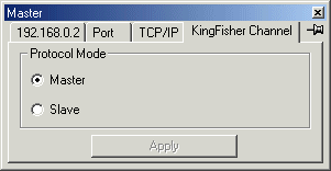
| Protocol Mode |
Choose Protocol Mode |
|---|
| Master |
IOServer will initiate all requests. |
|---|
| Slave |
IOServer will wait for and respond to requests. |
|---|
Device Configuration
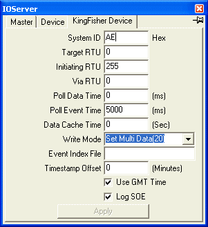
| System ID |
Sync character, use AE as default |
|---|
| Target RTU |
RTU for which this message is meant for. Use 0 for local RTU. Only one Master device need to configured to access the local and all remote RTU. |
|---|
| Initiating RTU |
RTU sending message. |
|---|
| Via RTU |
RTU to relay the message on to the target RTU |
|---|
| Poll Data Time |
How often to poll the update counter of each remote RTU. The data from the remote RTU will be extracted if its update counter is changed or when the data is first requested. The poll time for local RTU is set by the group update interval of the OPC client. A value of zero will disable data polls. |
|---|
| Poll Event Time |
How often to poll for time tagged data. A value of zero will disable event polls. |
|---|
| Data Cache Time |
Request data from remote RTU if no data is received from that RTU for the last Data Cache Time. A value of zero will disable cache polls. |
|---|
| Write Mode |
Analog Data Write Function Code
| Send Multi Network Data |
Write to local RTU with FC 19 |
|---|
| Set Multi Data |
Write to remote RTU with FC 20 |
|---|
| QSet Multi Data |
Write to remote RTU with FC 23 |
|---|
|
|---|
| Event Index File |
The last event poll index is stored in this file. The filename must be unique for each device. If this file is not specified, then IOServer will extract all events from the RTU at startup. |
|---|
| Timestamp Offset |
Add this number of minutes to all timestamps received from KF RTU |
|---|
| Use UTC Time |
If Enable, all timestamp read and written to the slave are assumed to be based on UTC(Coordinated Universal Time) time. Otherwise local time is used. Use of UTC time is recommended, it is the responsibility of each OPC client in different time zones to convert the UTC time to local time for display. |
|---|
| Log SOE |
Enable the logging of SOE to ios.log File. |
|---|
Variable Types
Notes:
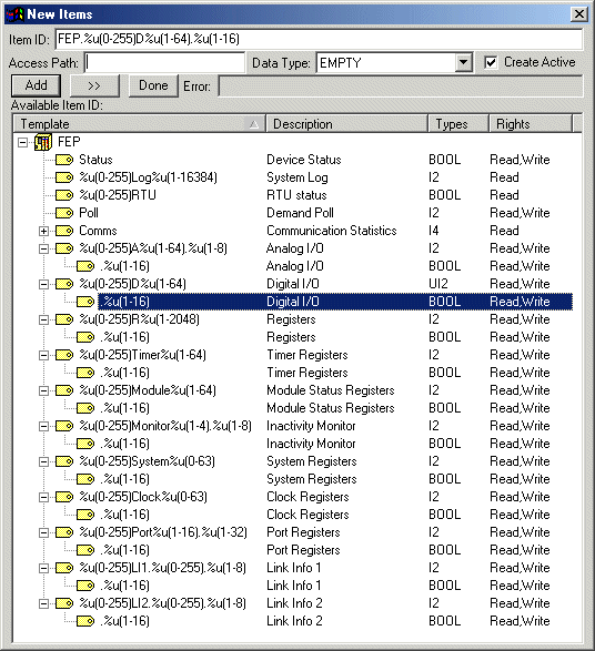
| %u(0-255) |
The prefix is the RTU number(0 to 255). Use 0 for the local RTU |
|---|
| Log |
System Log. Read Only events |
|---|
| RTU |
The status for RTU N (0 to 255). 0 for offline, 1 for online. The RTU is offline if the RTU Network Link Info 1, Last Fails register is not zero. |
|---|
| A |
Analog I/O for module M (1 to 64) and channel C (1 to 8) |
|---|
| D |
Digital I/O for module M (1 to 64) and channel CC (1 to 16) |
|---|
| R |
Register N (1 to 2048) |
|---|
| RE |
Register Event logs (1 to 2048) will be redirected to RE. Once any RE is read, register events will no longer to directed to R. |
|---|
| T |
Timer N (1 to 64) |
|---|
| Poll |
Write any value to this variable will cause all data to be refreshed from the RTU. |
|---|
| Module |
Module Status Register N (1 to 64) |
|---|
| Monitor |
Inactivity Monitor N (1 to 4) of 8 registers each |
|---|
| System |
System Parameters N (1 to 64) |
|---|
| Clock |
Clock Registers. Write a 0 to any Clock register will set the RTU to the current PC time. |
|---|
| Port |
Port Registers, Port 1 - 16 of 32 registers each |
|---|
| LI1 |
RTU Network Link Info 1. 8 registers for each RTU |
|---|
| LI2 |
RTU Network Link Info 2. 8 registers for each RTU |
|---|
| .%u(1-16) |
Bit 1 to 16 |
|---|
| Events |
Time tagged data from RTU event log are reported in the corresponding variable with the time stamp information as received in the event data. All received events are also log to the ios.log file. This feature requires a minimum license size of 10,000 bytes.
13:47:41.073 0.416 KFLog Master.20R11.2,1,1996 10 02 12:52:52.000
| 13:47:41.073 |
Time this event is received. |
| 0.416 |
Elapsed time since last event in log file. |
| KFLog |
Kingfisher Log tag |
| Master.20R11.2 |
Tag Name |
| 1 |
Value |
| 1996 10 02 12:52:52.000 |
Time as received in the event data |
13:47:41.074 0.109 KFLog Master.248Log5,0,1999 10 30 15:46:00.960
| Master.248Log5 |
System Log tag name | |
|---|
Reading Long and Real
Device2.24R1,R4
Will read R1 and R2 from RTU 24 for Device2 as 32 bit real. A real use two registers.
Device2.24R3,I4
Will read R3 and R4 from RTU 24 for Device2 as 32 bit long. A long use two registers.
Device2.24R1
Will read R1 from RTU 24 of Device2 as 16 bit word
See addtags.html for other data types.
|


