Channel Configuration
| Modbus Protocol Type |
Choose Modbus Protocol Type
| RTU |
Binary message format. 8 bits per data byte. |
|---|
| ASCII |
ASCII message format. 16 bits per data byte. |
|---|
| Ethernet |
Use Modbus/TCP message format. |
|---|
|
|---|
| Modbus Protocol Mode |
Choose Modbus Protocol Mode
| Master |
IOServer wil initiate all requests. |
|---|
| Slave |
IOServer will wait for and respond to requests. The slave can process requests from multiple masters at the same time. |
|---|
|
|---|
| Buffer Size |
Maximum of frame. 256 is the standard maximum frame size. |
|---|
| Initialization |
The initial command sent to the device to check if the device is online. In the form "BitAddress, Function Code, BitCount". The default value is "0,3,16".
| Function Code | Modbus Address | Data Type |
|---|
| 1 |
0xxxx |
Output Coils |
|---|
| 2 |
1xxxx |
Input Status |
|---|
| 4 |
3xxxx |
Input Registers |
|---|
| 3 |
4xxxx |
Output Registers |
|---|
| 7 |
E.x |
Exception Status |
|---|
|
|---|
Device Configuration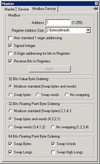
| Address |
Device address of slave. |
|---|
| Register Address Size |
Size of each register in the PLC. The default is two bytes per register location. |
|---|
| Non standard 1 origin addressing |
Add 1 to address when requesting data. |
|---|
| Signed Integer |
Treat all integers as signed. |
|---|
| 0 Origin addressing for bits in Registers. |
Bits in registers are numbered 0 to 15. The default numbering is 1-16. |
|---|
| Reverse Bits in Registers |
The bits numbering in registers are reversed |
|---|
| 32 Bits Value Byte Ordering |
Long value (4 bytes) byte ordering of device.
Device.40001,I4 will read the two registers at 40001 as a 32 bit signed integer value. |
|---|
| 32 Bits Floating Point Byte Ordering |
Single Precision Floating point numbers byte ordering of device.
Device.40001,R4 will read the two registers at 4001 as a 32 bit floating point value. |
|---|
| 64 Bits Floating Point Byte Ordering |
Double Precision Floating point numbers byte ordering of device. |
|---|
Variable Types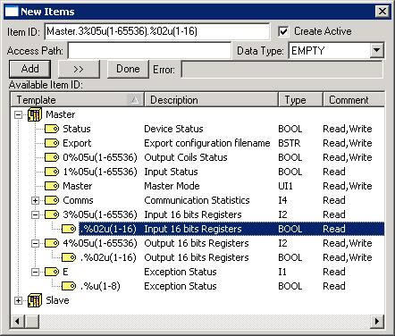
Modbus Channel Master Mode
| .Master Value |
|
|---|
| 255 |
Master Mode, issue read and write function codes to slave |
|---|
| 0 |
Issue write function code to slave, accept write function code from slave |
|---|
| n Seconds (1 to 254) |
Issue read function code to slave for next n seconds, issue write function code to slave, accept write function from slave |
|---|
Modbus Channel Slave Mode
| .Master Value |
|
|---|
| 255 |
Slave Mode, accept read and write function codes from master |
|---|
| 0 |
Accept read and write function codes from master |
|---|
| 1 |
Accept read and write function codes from master, issue write function code to slave |
|---|
Modbus Function Codes Supported
1, 2, 3, 4, 5, 6, 7, 15 and 16
Simulating Modbus Slave error
Writing a value with its 7th bit set to .E (Exception Status) in a Modbus Slave will cause it to response with that exception code to all requests. A value of 255 will stop it from responding.
Enron/Daniels Modbus Settings
Enron/Daniels Modbus Settings in IOServer
Register Address Size: 2 Bytes
Non standard 1 origin addressing
Signed Integer
32 Bits Value Byte Ordering: Swap bytes and words
32 Bits Floating Point Byte Ordering: Swap bytes and words
Registers Mapping
| Enron/Daniels | IOServer | Name |
|---|
| 1001-1999 |
01001-01999 |
Boolean |
|---|
| 3001-3999 |
43001-43999 |
16 bit Short integer |
|---|
| 5001-5999 |
45001,I4-46999,I4 |
32 bit Long integer |
|---|
| 7001-7999 |
47001,R4-48999,R4 |
32 bit Floating point |
|---|
When the Register Address size is set to 2 bytes, each 32 bits value occupies two register locations and their addresses must be odd.
When the Register Address size is set to 4 bytes, each 32 bit value occupies one register location. One device is configured with 4 bytes addressing to access the 32 bit values and second device with 2 bytes addressing to access the boolean and 16 bit values.
SMA Data Manager Settings
Use "480000,4,32" for initialization and Modbus Device.Non-standard 1 origin addressing set.
Modbus FAQ
Q:How do I access the two 16 bits registers at Device.40011 and Device.40012 as an IEE754 32-bit floating-point value.
A:Use the following tag syntax:
Device.40011,R4
See addtags for other data types.
Please make sure that the Modbus Device.32 Bits Floating Point Byte Ordering option is correct for your device.
Performance
IOServer running on a Pentium 4, 2.8 GHz PC under Windows 2000 Advanced Server reading from a remote device.
| Protocol | Requests per second |
|---|
| TCP/IP, 2 bytes per request |
2180 |
| TCP/IP, 250 bytes per request |
1392 |
| TCP/IP, 1450 bytes per request |
506 | |