System Port Configuration
| Protocol |
Selected Protocol |
|---|
| Port Name |
User supplied name for this port |
|---|
| Title |
Title of this protocol |
|---|
| Driver Name |
Name of this protocol |
|---|
| Description |
User description of this port |
|---|
| Transmit Delay |
Delay before transmitting each frame. |
|---|
| Timeout |
Time to wait for response before declaring a timeout error, the transmit time for the request and expected response at the current baud rate is automatically added to this value. |
|---|
| Retries |
Number of retries before giving up on the request and declaring an error. The device will go offline if the device does not respond to (Port.Retries + 1) * (Port.Retries + 2) consecutive retries. |
|---|
| Input Queue Length |
The maximum number of requests that is issued to the driver at any one time. Setting a value of 2 will allow the driver to send the next request as soon as it received the reply to the current request. |
|---|
| Watch Time |
Requests that are not serviced within the Watch Time by the driver are cancelled and declared with the command time out error. At each Watch Time Interval, IOServer will attempt reconnection to any failed devices. |
|---|
| Data Display Mode |
Show Data in Hex or ASCII mode
| Hex |
Display data in Hexadecimal format |
|---|
| ASCII |
Display data in ASCII format |
|---|
| Auto |
IOServer chooses the display mode (Hex or ASCII) that will use the shortest length. |
|---|
|
|---|
| Log Communication |
Log communication for this port if Log File.Communication Logging is set to Auto. |
|---|
| Expected Response Time |
Expected time taken to send and receive the reply to a read request in the form of "A + Bx" uSec based on time taken to read recent requests. A is the calculated overhead constant for all requests, B is the time required for each data byte requested. e.g. When using the Omron serial protocol at 19200, 7 data bits, no parity, 1 stop bits, 1 FIFO Byte. A is found to be 37845 and B is 795. To read two bytes should take 39,435 uSec (37845 + 795*2). To read 58 bytes should take 83,955 uSec (37945 + 795*58). |
|---|
| Blocking Gap (for Read Optimization) |
The Blocking Gap is A / B bytes. If the distance between two requests are less than "Blocking Gap" bytes then the two requests will be combined into one request. e.g. If the current "Blocking Gap" is 47 bytes. then requests for DM1 and DM23 will be combined into one request because the gap between DM1 and DM23 is less than 47 bytes. Because of the overheads in the protocol it is faster to issue one request for DM1,DM2, DM3 to DM23, than to issue two separate requests. A non-zero value will force the system to use that value as the blocking gap. |
|---|
| Correlation Coefficient |
Only Blocking Gap with a Correlation Coefficient of at least 0.95 will be used. When using TCP/IP or media with high transfer rate, the Correlation Coefficient will be low because of the high overhead in transferring each frame in Windows compared with the fast media speed. In this case it takes about the same amount of time to transfer 1 byte or 2048 bytes. If the Correlation Coefficient never get bigger than 0.95 then the Blocking Gap will be set to 2048 bytes. |
|---|
| Reset Values |
Reset all values to the default value for the driver. |
|---|
| Statistics |
| Errors |
Total number of errors other than timeouts or retries |
|---|
| Timeouts |
Total number of timeouts |
|---|
| Retries |
Total number of retries |
|---|
| Frames Tx |
Total number of frames transmitted (Frames transmitted per second) |
|---|
| Frames Rx |
Total number of frames received (Frames received per second) |
|---|
| Bytes Tx |
Total number of bytes transmitted (Bytes transmitted per second) |
|---|
| Bytes Rx |
Total number of bytes received (Bytes received per second) |
|---|
|
|---|
Write Optimization
When writing data to the PLC, IOServer can combine write requests into a single write request to the PLC as long as there are no gaps between the original write requests. eg. If you are writing to 00001,00002,00003,00004 ... to 00800 in a Modbus PLC, IOServer will issue a single write request to the PLC instead of 800 write requests.
Communication Event Log
This show all communication events on this port. If the IOServer->Preference->Display all communication events is not checked, then only errors are recorded. This data is also log to the log file if the Log all communication events option in IOServer->Log File is checked.
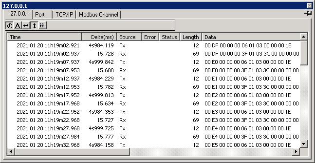
| Time |
Time this event was recorded. hour:minute:second.millsecond |
|---|
| Delta (ms) |
Time difference from previous event. |
|---|
| Source |
Tx - Data transmitted to this port, Rx - Data Received from this port |
|---|
| Error |
Error message for serial ports
| Rx Queue Overflow |
Operating system receive buffer overflow. |
|---|
| Rx Char Overrun |
UART receive FIFO overflow. |
|---|
| Rx Parity |
Received character with parity error. |
|---|
| Rx Frame |
Received character with framing error. |
|---|
| Rx Break |
Received break character. |
|---|
| Tx Queue Full |
Operating system transmit buffer overflow. |
|---|
| Tx wait CTS |
Transmitter is waiting for CTS to be asserted. |
|---|
| Tx wait DSR |
Transmitter is waiting for DSR to be asserted. |
|---|
| Tx wait DCD |
Transmitter is waiting for DCD to be asserted. |
|---|
| Rx XOFF |
Received XOFF character. |
|---|
| Tx XOFF |
Transmitted XOFF character. |
|---|
|
|---|
| Status |
Special indications for serial ports
| CTS |
Clear to Send is on. |
|---|
| DSR |
Data Set Ready is on. |
|---|
| DCD |
Data Carrier Detect is on. |
|---|
| RING |
Ring indicator is on. |
|---|
| In(count) |
There arestill count number of characters in the operating system receive buffer. |
|---|
| Out(count) |
There are still count number of characters to be transmitted. |
|---|
|
|---|
| Length |
Number of bytes transmitted or received. |
|---|
| Data |
Actual data transmitted or received. |
|---|
|